Showing posts with label electronics. Show all posts

Sunday, November 24, 2013

Another 3D Print - Star Wars Tie Fighter

Last week suddenly I heard a noise and I saw the extruder of the 3D printer I build hanging on only one screw. I tried to fasten everything again, but I had no luck what so ever. So before I could do any more printing I had to take the whole extruder apart, fasten the screws a but more and put it back together. That was a little setback, but unfortunately it didn't end there. After that I had to recalibrate the head distance and I had no luck in that.

The material just didn't want to stick to the heated print bed anymore. I tried cleaning with alcohol, rubbing it a bit with sand paper like I did before, but no luck. Then I started looking on some forums for a solution and I found one. Painters tape! Very cheap stuff that you can just stick on the print bed and after that I printed like a charm. I guess by now you would have guessed from seeing the pictures of a print in progress.

The model I printed came from ThingiVerse and it is a tie fighter from Star Wars. I really like the look of that model. It consisted of three separate printable parts that you eventually have to glue together. But before I got to this point there was some more trouble. After the first print was finished, the material was stuck to the painters tape so well, that I couldn't get it off. I printed in PLA and that is quite fragile, so I could not use too much force since then the material would break.

So again I went to look for a solution and I found one. The tip was to use a spraycan with compressed air, put it up side down on purpose so that the stuff coming out is frozen. This cools the object to quickly that it shrinks a bit and pops loose. And guess what? It worked :) I will go and look now though for blue painters tape since they say this is less sticky. So that is worth the experiment. All in all the model is done and I really like it. But again I found out that printing on a DIY 3D printer is not so easy as it looks. Ah well most important thing. It still works. Up to the next project.

Sunday, November 10, 2013

Velleman K8200 3D Printer (Part 6)

I know it has been a while since I wrote on here and that some of you are waiting on the final part of this series about the Velleman K8200 kit. I have been very busy lately with my new company Virtiso BV and didn't have much time for anything actually. But today finally I found some time to catch up on here. First of all here is a picture of the finished printer doing its first test prints. As I wrote before though this didn't go as I planned.

On the picture on the right you can see what happened on my first test prints. I was quite puzzled and had no idea what to do next, since the manual ended here. I started reading a bit on several forums and started asking around. The first thing I learned (and it is in the manual now) that you really need to roughen up the print bed a bit with some sand paper. It is just to smooth as it comes. Secondly you really need to clean it with some alcohol. This has to be 70% the least, but more is better. This is because when you touch it with your fingers it will become greasy.


And then I think the hardest part was calibrating the print head Z distance. The head needs to be exactly 0,25 mm from the bed. And in every direction. So you need first to level the print bed with the screws below and then you need to turn a screw that touches a microswitch to calibrate it. I tried to do that on eyesight, but that really is impossible. You need a tool like you see in the picture on the left. I don't know what it is called in English though but it consists of small metalic blades that you can use to 'feel' the distance of the head to the bed. When you can put the 0.2 5mm blade just in between and you feel some friction it is OK. Then don't forget to securely fasten the calibration screw since it will come loose from vibration.

And then you need to calibrate the software settings as well depending on your material and print object. It took me about as long to calibrate the printer as it took me to build it. So do keep this in mind. Printing in 3D is not as easy as it looks at first sight. It takes time, skill and a lot of patience :) Then I had another problem that turned out to be the USB driver on windows. I finally swapped to a RaspBerry Pi running Octoprint and in the picture on the right is the first part that was finally printed successfully. What it is I'll show you in a later post ;) This concludes the building series. I hope to post some stuff that I printed over time on here. I'll keep you updated when I can.

Saturday, August 31, 2013

Velleman K8200 3D Printer (Part 5)

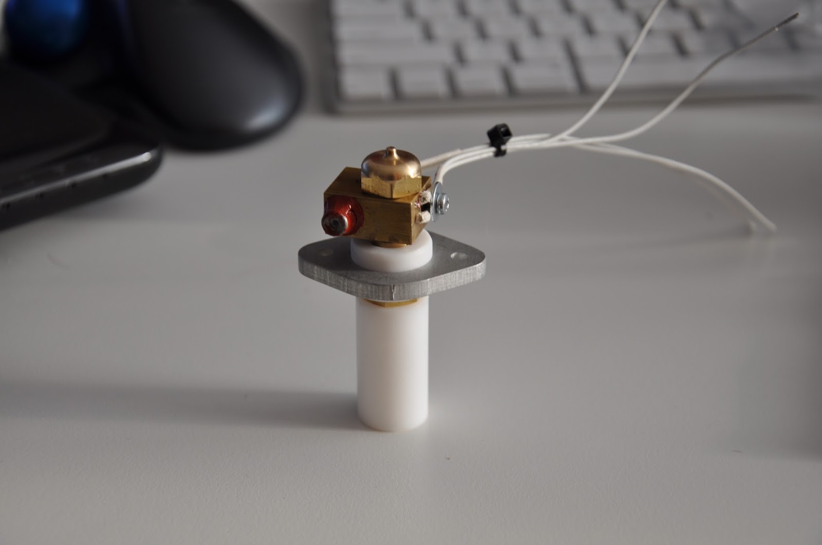
Another very critical and not so easy part of building the K8200 3D printer is assembling the hot end. This is where is plastic eventually will be heated to 190 degrees C with PLA and even higher with ABS. To keep the temperature steady a tiny NTC has to be inserted in a very small whole in the heater. The wires are about as thin as a hair and you have to solder them to the thicker wire, put heat resistant tube around it and make sure none of the leads touch each other and don't touch the copper either.

If you make a mistake here or don't insert the NTC resistor properly in the whole your temperatures will be off and your prints will fail. You need a lot of patience here :) On the right is a picture of the whole hot end. It is actually up side down. Eventually the plastic flow from the little hole on top of the copper nozzle. This is the print head and it will be about 0,25 mm from the print bed. Another remark is in the manual that you need to tighten all of this very good to prevent leakage that will be unrepairable and will cost you a new hot end. So again. Patience and check and double check everything.

The it is time to install the control board and solder all the wires. Not a very exiting job but again you need patience and some soldering skills. The manual is quite extensive about which wire goes where and shows a lot of pictures. So if you follow along carefully you can't go wrong there. When you are finished you wrap everything up neatly with some tie raps and you can do some sanity checks with your multimeter to see if there is no short circuits anywhere.

And then you are done building, but not finished by far. The first step is calibrating the stepper motor voltages. You need a multimeter and a very small screw driver for this and again patience :) Then you test the switches with the multimeter and measure the NTC's. And then the famous smoke test. Hook up the power, watch the leds and see if nothing smokes. When that is done it is time for some actual testing from the software and seeing if all the motors run and if the calibration works. So far so good. I'm happy to say that everything was working for me the first time. But the story isn't over yet :) The hardest part turned out still to come. More on that soon.


Sunday, August 25, 2013

Velleman K8200 3D Printer (Part 3)

I didn't have much time lately to continue this report, but now I did so here it continues. Next part in building the printer was constructing the frame. It is made of clever aluminum struts held together by 90 degree angled clamps. I never saw this stuff before, but it is really cool you can build anything with this I guess. Tricky part is you really need to read the manual here since you have to insert some square nuts in there that you will need later.

After that you insert the X/Y carriage that was constructed before. Aligning is a careful job as well. It has to be positioned very well. The cool thing is after this you are able to move it around and get a sense of what it will be like when it is printing. I was quite happy that everything seemed to move very smoothly so I could go on to the next part. Down side is now that it is getting quite a large piece to work on so I had to continue my work on the floor.

Then you start building your way up. These two assemblies on the left and right will eventually move the print extruder assembly up and down. So this is for the Z movement. On the left is another motor with a long piece of threaded material attached the drives an embedded bolt. On top you have to apply quite some force to screw on a lock tight bolt. It is quite difficult to hold it all. You have to be especially careful not the damage the thread since it will make smooth movement problematic later on.

And the last part is to install another piece of aluminum strut on top to hold everything together. I didn't follow the manual here on purpose. The bar is supposed to go lower with a bracket on top, but I thought it didn't look as nice and I preferred to mount it like this. I could not think of any problem this would create since the whole construction was still rock solid. And it really necessary I could always change this later on. So far so good. Everything still running smoothly also by turning the motor for the Z movement. It is really starting to look like a real machine already :)